MiRS Sensors
MHS Overview
Satellite(s)
N-18, N-19, MetopA, MetopB
MiRS Production Status
Currently operational.
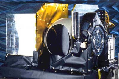
The Microwave Humidity Sounder (MHS) is a self-calibrating microwave radiometer, observing the Earth with a field of view of ±50 degrees across nadir, in five frequency channels of the millimeter-wave band (89-190 GHz). MHS, together with the complementary AMSU-A instruments, provides the operational microwave sounding capability for the NOAA-N, -N' meteorological satellites.
Channels at 157 GHz and around the 183 GHz water vapor absorption line provide a humidity profile sounding capability, while the 89 GHz channel provides information on surface temperature and emissivity (in conjunction with AMSU-A channels) and detects cloud and precipitation contaminated pixels. The MHS instrument represents an improvement to the AMSU-B radiometer on board previous NOAA satellites, while providing continuity to its data. Two MHS instruments are planned to fly on NOAA-N and -N' satellites, and three on the METOP satellite series of the European Polar System (EPS).
MHS is a cross-track, line-scanned instrument. Ninety contiguous scene resolution cells are sampled in a continuous scan, covering 49.44444... degrees on each side of the sub-satellite path, with an antenna beam width of 1.11111... degrees at half power point. These scan patterns and geometric resolution translate to a 17-km diameter cell at nadir from the 870 km nominal orbital altitude.
A parabolic mirror is rotated to sample the Earth scene at 90 equidistant angular positions, at a rate of three scans every eight seconds, and at the same time to provide reference measurements against two calibration sources, i.e. an on-board blackbody target and a view on free space. The radiation is then conveyed on four feeds at 89, 157, 183 and 190 GHz via a "quasi-optical" arrangement of lenses, dichroic plates and a polarizing beam splitter.
| Channel (See Note 1) |
Central Frequency (GHz) |
No of Passbands | RF Bandwidth (MHz)(See Note 2) |
T (K) (See Note 3) |
Polarization (See Note 4) |
|---|---|---|---|---|---|
| H1 | 89.0 | 1 | 2800 | 0.22 | V |
| H2 | 157.0 | 1 | 2800 | 0.34 | V |
| H3 | 183.311 ± 1.0 | 2 | 2 x 500 | 0.51 | H |
| H4 | 183.311 ± 3.0 | 2 | 2 x 1000 | 0.40 | H |
| H5 | 190.311 | 1 | 2200 | 0.46 | V |
Notes:
- The five MHS channels provide data continuity with AMSU-B channels 16 to 20, with some minor changes in frequency allocation and polarization, and improved performance.
- The quoted values for the maximum bandwidths are double-sideband values and represent the maximum permissible bandwidths at the 3 dB points.
- Ground measured values for the first flight model (NOAA-N).
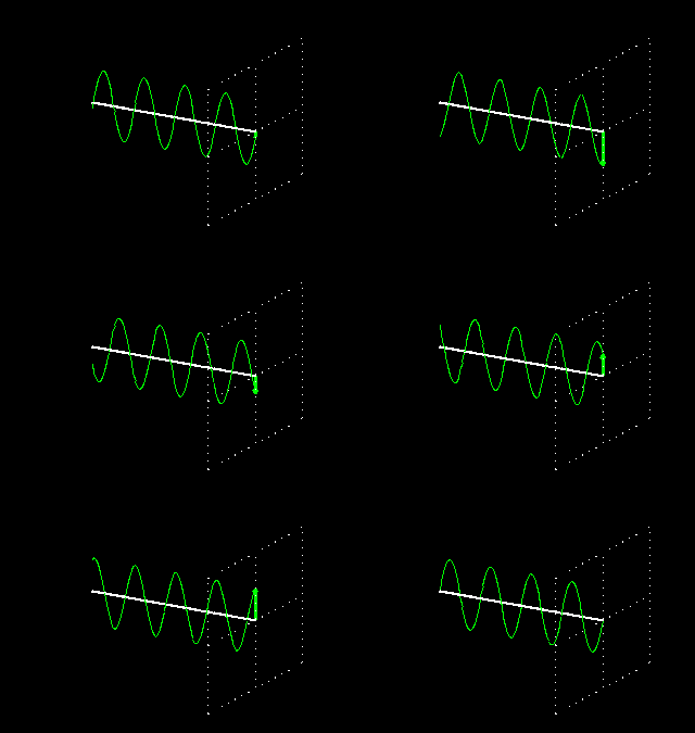
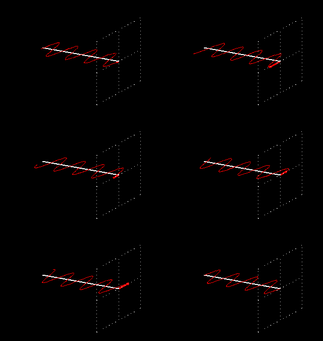
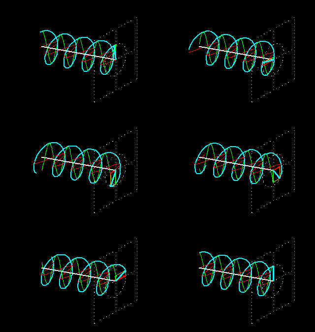
- The V and H polarizations correspond respectively to electrical fields normal or parallel to the ground track at nadir, both rotating by an angle equal to the scan angle for off-nadir directions.
* From NOAA KLM User's Guide

