GOES Imager Projection (ABI Fixed Grid)
Information on this page is adapted from the GOES-R Series Product Definition and User’s Guide (PUG), Volume 5: Level 2+ Products, Section 4.2.
What is the GOES Imager Projection?
The GOES Imager Projection, also called the ABI Fixed Grid, is the projection information included in all ABI Level 1b radiance data files and most ABI Level 2 derived product data files. It is a map projection based on the geostationary viewing perspective of the GOES-East or GOES-West satellite.
The GOES Imager Projection information is used instead of latitude and longitude, to save ABI data file space. As a result, latitude and longitude are not included as separate variables in most ABI data files, including the Level 2 files we use in our training sessions (e.g., ADP, AOD, FDC).
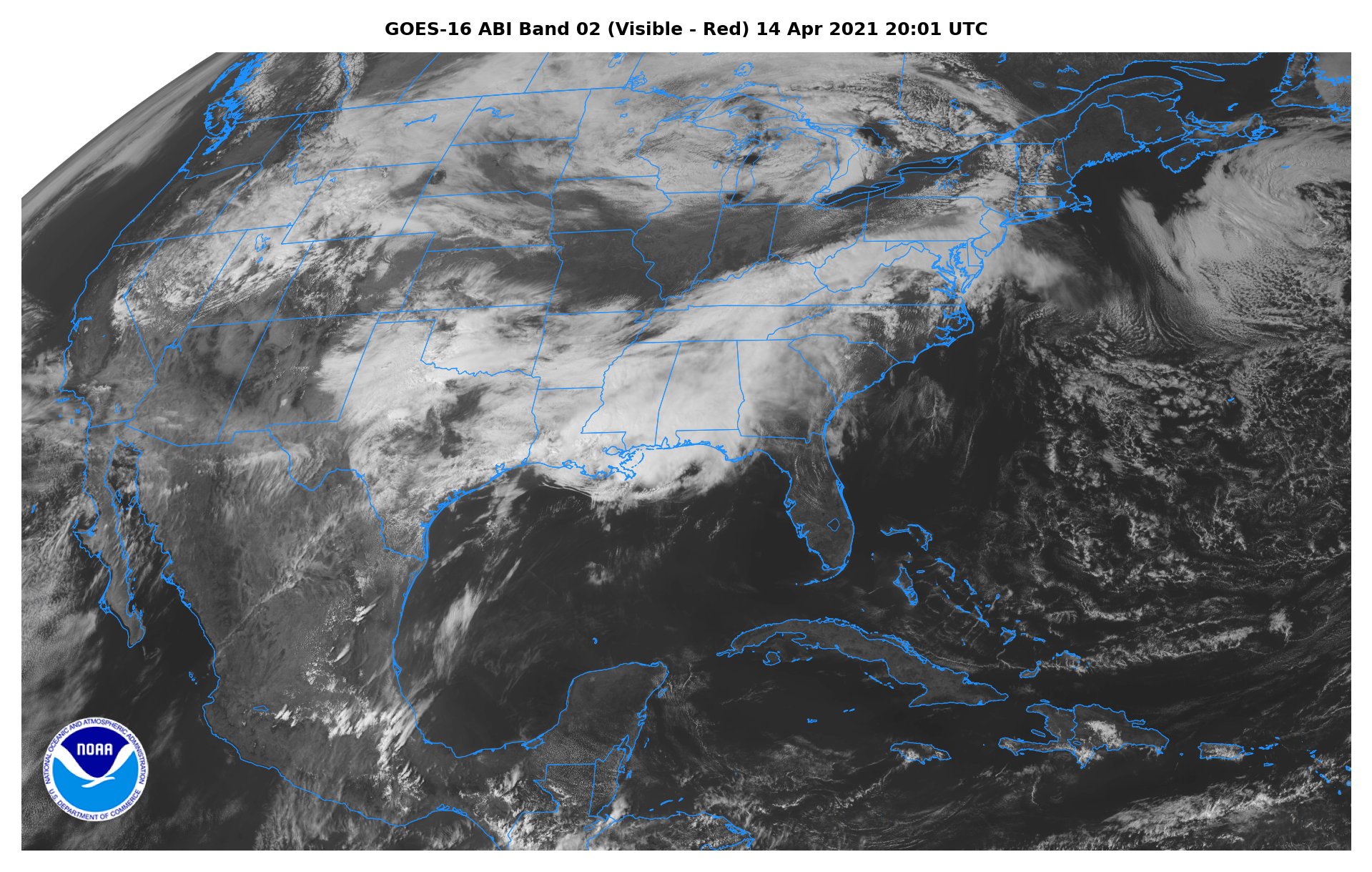
What does this mean for you as an end user? It is possible to work with ABI data using the GOES Imager Projection directly; an example of GOES-16 ABI CONUS sector band 2 radiance (L1b) data visualized using the GOES Imager Projection is shown below. Note the distinctive “curved” view of the Earth from the geostationary satellite projection (click image to open full size version).
Calculating Latitude and Longitude from the GOES Imager Projection
If you want to work with ABI Level 2 files using latitude and longitude to plot the data variables (e.g., ADP, AOD, FDC), then it is necessary to calculate latitude and longitude from the GOES Imager Projection information.
The figure below shows the coordinate frames for the latitude/longitude calculations. For a given point P on the Earth with ABI fixed grid coordinates (y, x), the latitude (φ) and longitude (λ) can be calculated using a series of equations, provided in the GOES-R PUG.
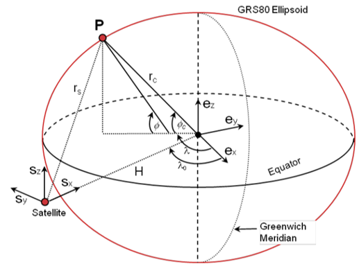
Coordinate Frames for GOES Imager Projection (ABI Fixed Grid) Navigation
(image courtesy of GOES-R PUG; click image to open it in a separate tab)
All of the information needed to calculate latitude and longitude are provided in the ABI data file:
- x variable (fixed grid E/W scanning angle in radians)
- y variable (fixed grid N/S elevation angle in radians)
- req (semi-major axis)
- rpol (semi-minor axis)
- H (perspective point height + semi-major axis)
- λ0 (longitude of projection origin)
Don’t worry! We did the math for you. We provide a Python function that can be used to calculate latitude and longitude from the GOES Imager Projection information in any ABI Level 2 data file.
Download Files Containing Latitude and Longitude for 2km Resolution Full Disk & CONUS Sectors
If you are working with ABI Level 2 files for the full disk or CONUS sectors, it can be easier to read in the latitude and longitude arrays for the ABI fixed grid from external netCDF4 (.nc) files, instead of calculating the latitude and longitude arrays on the fly from the GOES Imager Projection information in the Level 2 file.
Below are .zip files that contain the latitude and longitude .nc files for the current GOES-East and GOES-West full disk and CONUS sectors at 2km spatial resolution, which is the resolution for ADP, AOD, and FDC data files.
There are two options available for the latitude and longitude .nc files: original and interpolated. Download the option you prefer & extract and save the .nc file, and then you can simply open it and read in the latitude and longitude arrays.
- The original files contain missing latitude & longitude values, represented by a fill value or "NaN", corresponding to the regions where the satellite is viewing outer space and not the Earth’s surface; this occurs for both full disk sectors and for the GOES-East CONUS sector.
- The interpolated files are identical to the original files except the missing latitude and longitude values have been interpolated. The interpolated latitude and longitude values have no physical meaning, since they correspond to space. Use the interpolated files for applications that don't allow latitude or longitude arrays to have missing or masked values, such as Matplotlib's pyplot.pcolormesh plotting function.
Full Disk & CONUS sector (2km resolution) ABI fixed grid latitude and longitude .nc files
- GOES-East (GOES-19, 75.2 °W) 2km resolution Full Disk sector:
- GOES-East (GOES-19, 75.2 °W) 2km resolution CONUS sector:
- GOES-West (GOES-18, 137.0 °W) 2km resolution Full Disk sector:
- GOES-West (GOES-18, 137.0 °W) 2km resolution CONUS sector:
If you are working with Mesoscale sector files, then you will have to use the provided Python function to calculate the latitude and longitude arrays on the fly from the GOES Imager Projection information in the ABI Level 2 file. This is because unlike the full disk & CONUS sectors (whose locations do not vary), the locations of the Mesoscale sectors change depending on current hazards.
Download File Containing Latitude and Longitude for Hourly Surface PM2.5 Estimated from ABI/TEMPO
The Level 3 hourly surface PM2.5 concentration products estimated from ABI/TEMPO are gridded on the GOES-East and GOES-West ABI CONUS sector fixed grids; the GOES-East grid is used for data located east of 106 °W longitude, and the GOES-West grid is used for data located west of 106 °W longitude. The hourly estimated PM2.5 files include latitude and longitude variables for these grids, but because they use the ABI fixed grid and therefore do not vary, it can be easier to read in the latitude and longitude arrays from an external netCDF4 (.nc) file. The hourly estimated PM2.5 latitude and longitude grids in the Level 3 file contain missing values, which will cause an error when using applications that don't allow latitude or longitude arrays to have missing or masked values, such as Matplotlib's pyplot.pcolormesh plotting function.
Below are .zip files that contain the latitude and longitude .nc file for the hourly surface PM2.5 products estimated from ABI/TEMPO.
There are two options available for the latitude and longitude .nc files: original and interpolated. Download the option you prefer & extract and save the .nc file, and then you can simply open it and read in the latitude and longitude arrays for the hourly estimated surface PM2.5 concentrations.
- The original file contains missing latitude & longitude values, represented by a fill value or "NaN", which correspond to locations west of 106 °W longitude on the GOES-East grid and east of 106 °W longitude on the GOES-West grid.
- The interpolated file is identical to the original file except the missing latitude and longitude values have been interpolated. Use the interpolated file for applications that don't allow latitude or longitude arrays to have missing or masked values.
Hourly surface PM2.5 estimated from ABI/TEMPO fixed grid latitude and longitude .nc files